N+1: Cost Effective Automated Transmitter Backup
Nautel designs extreme reliability and redundancy into all Nautel transmitters to help ensure that broadcasters stay on air. However, for facilities that broadcast multiple programs from a single site, N+1 capability provides even higher levels of redundancy that is automated and cost effective. Nautel N+1 configurations support up to eight identical main transmitters plus a backup transmitter serving outputs of 150 watts to 40 kilowatts of solid-state power.
N+1 Solution Features and Advantages
- Reduce the need for multiple back-up transmitters while maintaining high reliability
- Cost savings
- Automatic switchover back up
- Facilitates easy maintenance while keeping station on air at full power
- Station back up prioritization: Key station(s) take priority over lower priority stations
- Full power backup transmitter
- Automated program routing to standby transmitter
- Complete isolation of the +1 transmitter when it is off-air
- Remote control
4+1 Implementation Example
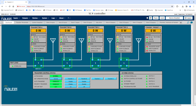
In this example four Nautel GV Series FM broadcast transmitters (A through D) plus one backup transmitter are configured with a series of coaxial switches that are part of a 4+1 switch matrix, and a Nautel SC4 controller.
![]()
Each transmitter (A through D) operates individually at one frequency between 87.5 MHz and 108.0 MHz. The system is designed to allow the backup transmitter to be used in place of any one of the main transmitters in the event of a main transmitter failure. The +1 transmitter can back up only one transmitter at a time. A 50 ohm load acts as the test load for the backup transmitter or the transmitter that the backup is replacing.
When the SC4 recognizes a fault condition that has inhibited output power of any of the on-air transmitters, the SC4 inhibits the faulty transmitter and transfers it to a test load. The SC4 configures the program router to assign the appropriate program to the +1 transmitter and adjusts the frequency and power settings of the +1 transmitter accordingly. This enables it to broadcast on the faulty transmitter’s channel.
![]()
When priority transfer is enabled, the system automatically prioritizes transmitter 1, then 2, and so on up to N. This priority sequence cannot be changed. If a higher priority transmitter fails after a transfer to a lower priority one, the +1 transmitter steps in to replace it, routing its signal through the higher priority transmitter’s antenna. The failed higher priority transmitter is directed to a test load and deactivated, while the lower priority transmitter resumes broadcasting through its antenna. If priority transfer is disabled, the system switches transmitters based on a first-come-first-served approach.
Additional Implementation Details
- Each transmitter is single channel, has its own audio, and frequency.
- The +1 transmitter must be able to broadcast each of the other transmitters programming.
- The transmitter system is controlled by the Nautel SC4 system controller. The SC4 provides all the control, monitoring, and metering circuitry for the N+1 FM transmitter system.
- The SC4 system controller delivers the ‘program select’ control signal to the audio program switcher, directing it to choose the suitable program inputs for the backup transmitter.
- The N+1 switch matrix contains N motorized coaxial switches (S1 through SN), one for each of the N main transmitters. Each switch controls the routing of its associated transmitter’s RF output, either directing it to an antenna output or to the dummy load. The position of these switches is controlled by the SC4 system controller.
- All RF outputs go to one common antenna or are configured to go to separate antennas.
- If a common antenna is used, the RF outputs go through a channel combiner after the switch matrix.
SC4 Controller
Nautel’s SC4 Controller, powered by Davicom, is an SNMP-based system controller pre-configured for Nautel transmitters and available in Main/Standby and N+1 configurations. It’s designed to offer advanced control and monitoring capabilities, featuring a sophisticated HTML5 remote user interface for instantaneous updates and remote changeover control management.
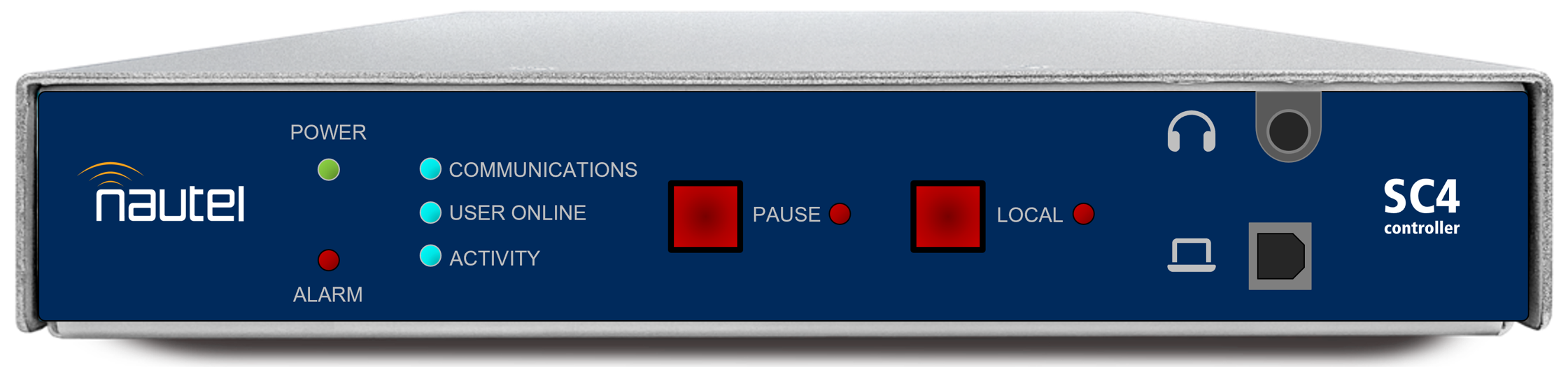
SC4 Remote User Interface